TIN Surface Direct Modeling
Commands
TINEXTRACT, TINMODIFY, TINMERGE
Overview
In BricsCAD, topographical surfaces created as a TIN Surface, can be adjusted using different tools.
About TINEXTRACT
The TINEXTRACT command is used to generate a solid, mesh, border, intersection lines, faces and points from a TIN surface. You can exchange these entities in other applications, to further analyze the surfaces. The solids or meshes can be created in different ways: as a vertical offset of the TIN Surface, as a model between two TIN Surfaces or as a model between a fixed elevation plane and the TIN Surface.
Procedure: Creating a solid from a TIN surface using option Elevation
- Select a TIN Surface and type TINEXTRACT in the Command line.
- The Extract From TIN Surface dialog box opens. Set the Solids/Meshes option to On.
- Tick the Elevation button and set a value for height.
- Press the Extract button.

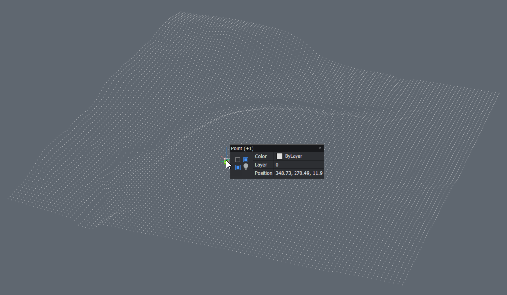
Procedure: Creating Points from a TIN surface
- Select a TIN Surface and type TINEXTRACT in the Command line.
- The Extract From TIN Surface dialog box opens.
- Tick the Points option and, optionally, select the desired layer.
- Press the Extract button.
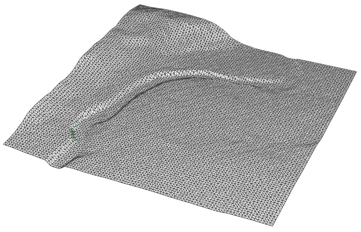
Procedure: Creating Faces from a TIN surface
- Select a TIN Surface and type TINEXTRACT in the Command line.
- The Extract From TIN Surface dialog box opens.
- Tick the Triangles option and, optionally, select the desired layer.
- Press the Extract button.
Procedure: Creating a Contours from a TIN surface
- Select a TIN Surface and type TINEXTRACT in the Command line.
- The Extract From TIN Surface dialog box opens.
- Tick the Major contours and Minor contours options and, optionally, select the desired layers.
- Set the Interval values for both major and minor contours.
- Press the Extract button.

Procedure: Creating a Border from a TIN surface
- Select a TIN Surface and type TINEXTRACT in the Command line.
- The Extract From TIN Surface dialog box opens.
- Tick the Borders option and, optionally, select the desired layer.
- Press the Extract button.

About TIN Merge
Different TIN Surfaces can be merged into one by using the TINMERGE command. A merge is executed between a base surface and one or more surfaces to merge with.
Merging TIN Surfaces
- Type TINMERGE in the Command line.

- Choose a base surface. In this example, we choose the green surface as the base surface.
- Choose to keep or delete the original surfaces.Note: Selecting a different baseline, results in a different merge. It is important to remember that the surface to merge replaces the part of the base surface that it covers.
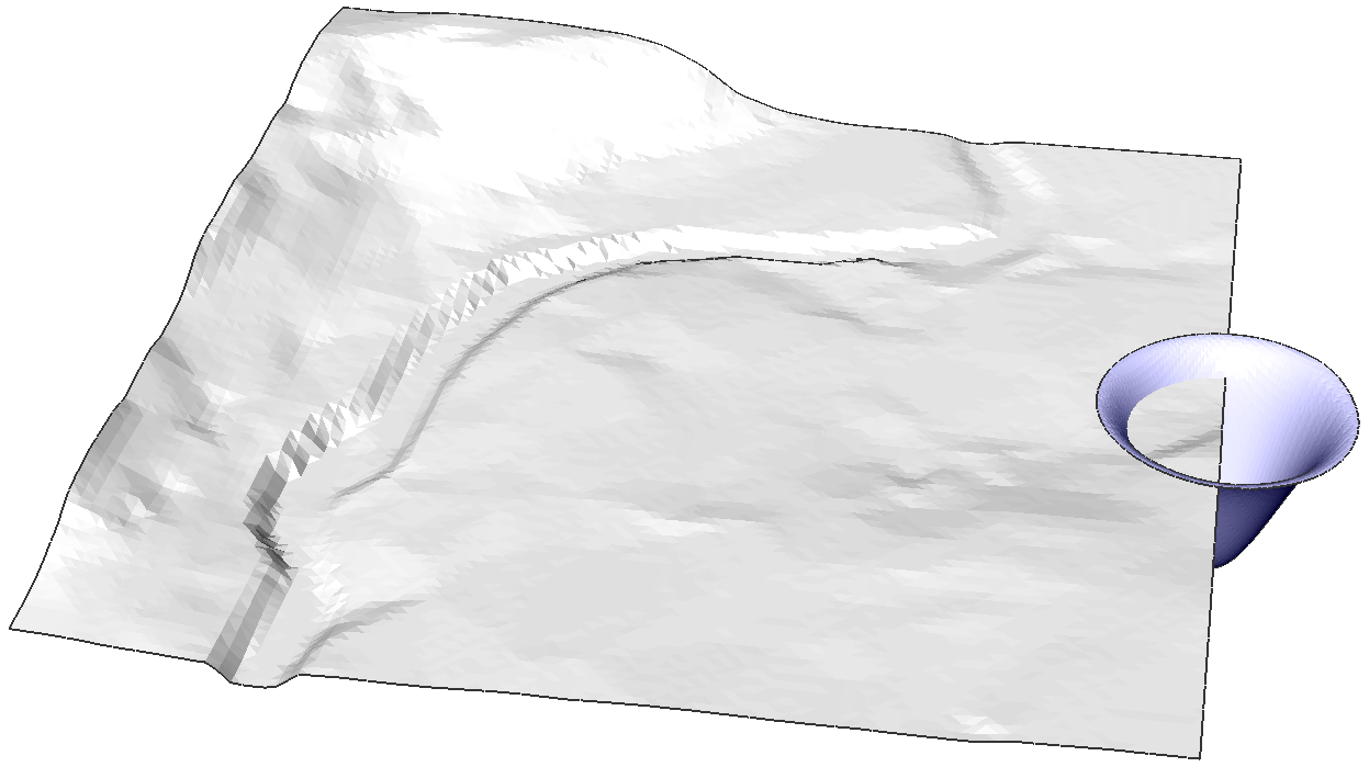
The first example shows the merge of the green surface as the base surface and the blue and red surface.
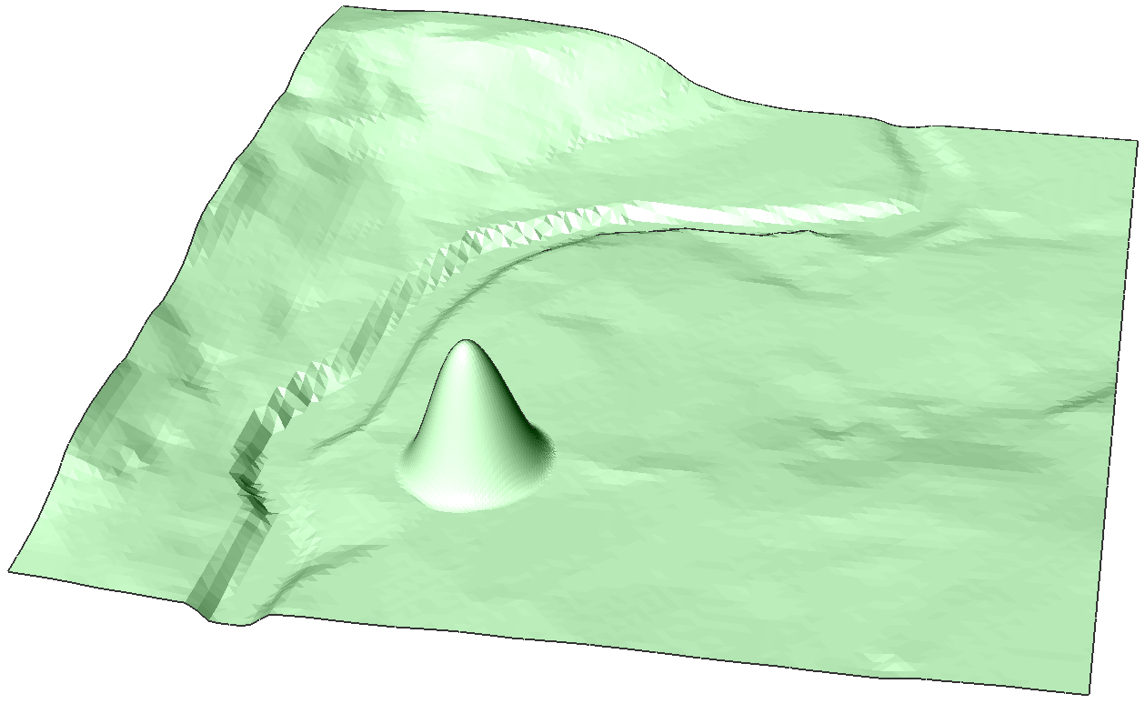
The second surface shows the merge of the blue surface as the base surface and the green surface.
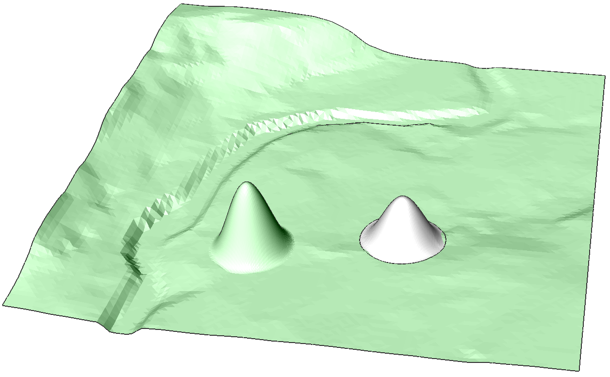
The third surface shows the merge of the red surface as the base surface and the green surface.
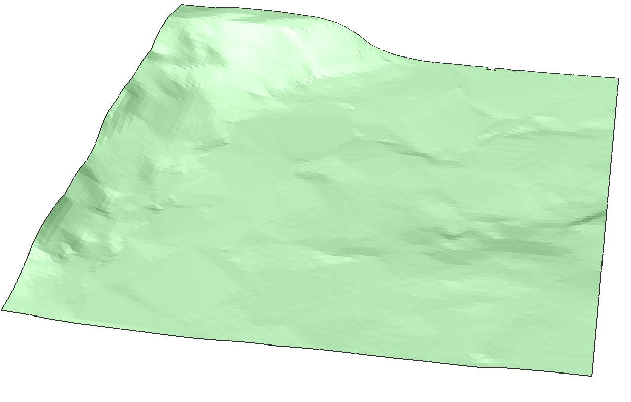
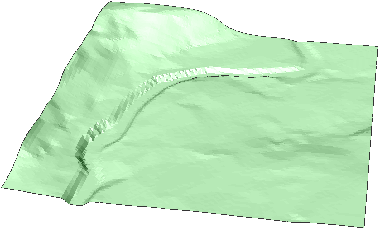
About TIN Modify
A TIN Surface can be modified by deforming or smoothening the surface. By deforming the surface, the TIN Surface is adjusted following the contours of an area defined by the user. By smoothening the surface, a selected area is leveled which is done by interpolation of this predefined area.
Procedure: Adding deformations on a TIN Surface using Radius
- Select a TIN Surface and type TINMODIFY in the Command line.
- Select the Deform option.
- Choose a deformation radius.
- Click the area to apply the deformation.
- Choose the elevation height.
- Choose whether you want to add the adjustment as a new element or as a modification of the existing TIN Surface.
 Note: By adding the modification as a new element, the structure of the original TIN Surface isn't modified but added as a new TIN surface.
 - Click other areas to add new deformation or press Enter to end the command.
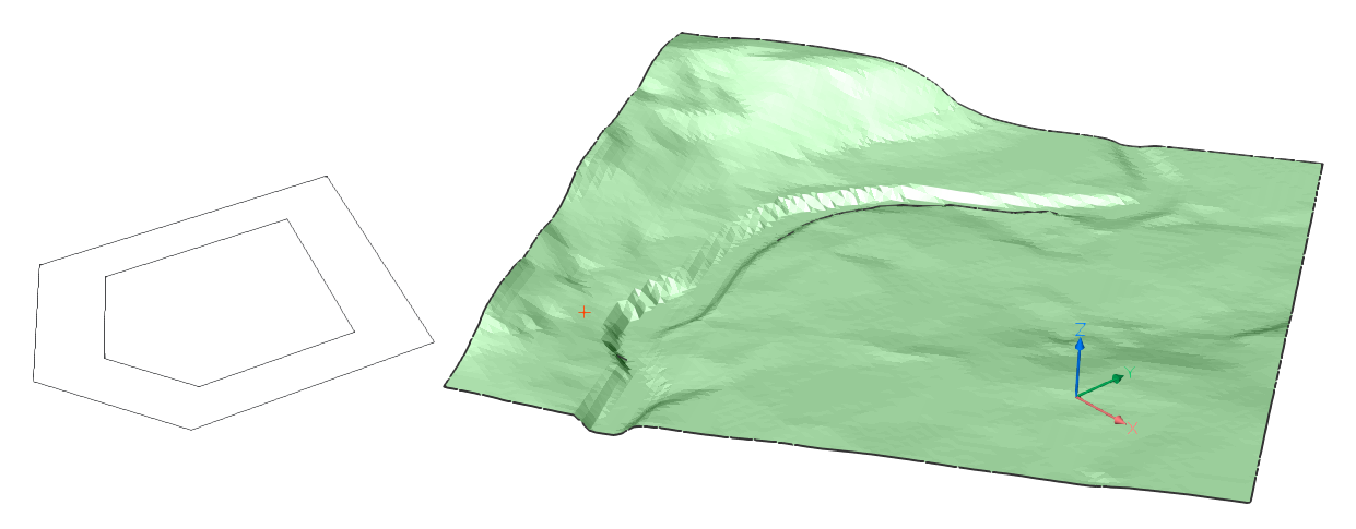
Procedure: Adding deformations on a TIN Surface using specify Contour
- Select a TIN Surface and type TINMODIFY in the Command line.
- Select the Deform option.
- Select the specify Contour option.
- Pick a contour on the TIN Surface.
- Choose whether you want to add the adjustment as a new element or as a modification of the existing TIN Surface. Type N to create a new element for the adjustment.
- Click other contours to add new deformation or press Enter to end the command.
- You have now created a new element on your TIN Surface. You can change its properties as you like. For example: change the color of the element.

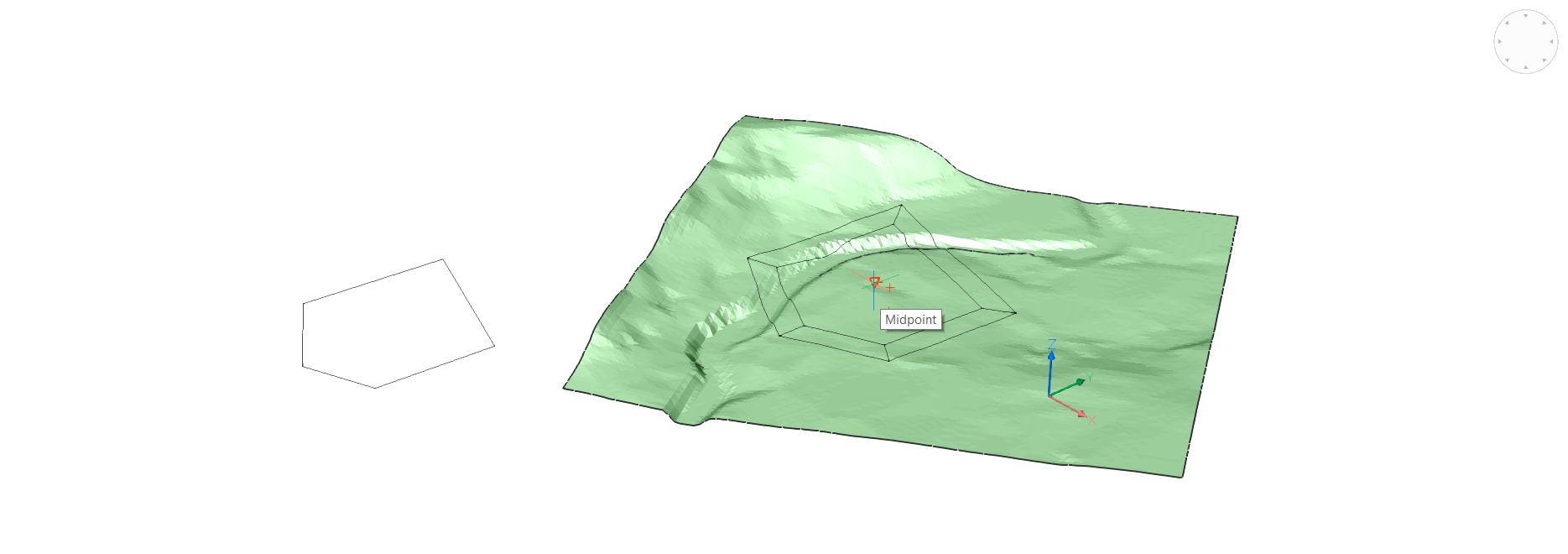
Procedure: Adding deformations on a TIN Surface using select Entity
- Select a TIN Surface and type TINMODIFY in the Command line.
- Select the Deform option.
- Type E and hit Enter to choose Select Entity.
- Select a closed entity (for example, Polyline).
- Choose an offset distance.
- Click the area to apply the deformation.
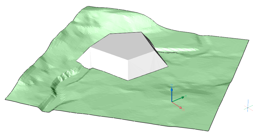
- Choose the elevation height.
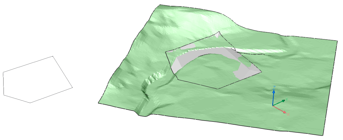
- Choose whether you want to add the adjustment as a new element or as a modification of the existing TIN Surface. Type N to create a New element for your adjustment.
- Click other areas to add new deformation or press Enter to end the command. You have now added a deformation using select Entity.
Procedure: Adding deformations on a TIN Surface using draw Polygon
- Select a TIN Surface and type TINMODIFY in the Command line.
- Select the Deform option.
- Select draw Polygon.
- Draw a polygon, hit Enter to close the polygon.
- Choose an offset distance.

- Select the area where to apply the deformation.
- Choose the elevation height.
- Choose whether you want to add the adjustment as a new element or as a modification of the existing TIN Surface. Type N to create a new element for your adjustment.
- Click other areas to add new deformation or press Enter to end the command. You have now added a deformation using draw polygon.
Procedure: Smoothening a TIN Surface
- Select a TIN Surface and type TINMODIFY in the Command line.
- Select the Smoothen option.
- Choose a radius.Note: The procedure for select Entity or draw Polygon is analogue to Adding deformations using select Entity and Adding deformations using draw Polygon starting from step 3.
- A preview of the intervention is shown.
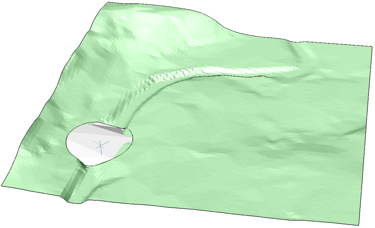
- Click to execute the command.
- Click other areas to smoothen or press Enter to end the command.