Working with Point cloud
Commands
POINTCLOUD command, POINTCLOUDALIGN command, POINTCLOUDATTACH command, -POINTCLOUDATTACH command, POINTCLOUDCOLORMAP command, POINTCLOUDCROP command, POINTCLOUDCROPSOLID command, POINTCLOUDDELETEITEM command, POINTCLOUDDETECTFLOORS command, POINTCLOUDEXPORT command, POINTCLOUDFITPLANAR command, POINTCLOUDIMPORT command, POINTCLOUDPOINTSIZE_MINUS command, POINTCLOUDPOINTSIZE_MINUS command, POINTCLOUDPOINTSIZE_PLUS command, POINTCLOUDPREPROCESS command, -POINTCLOUDPREPROCESS command, POINTCLOUDPROJECTSECTION command, POINTCLOUDREFERENCE command, POINTCLOUDSHOWBUBBLES command, POINTCLOUDUNCROP command, POINTCLOUDPOINTMAX system variable
Point cloud functionality is significantly faster and more powerful in BricsCAD v21 and is even more powerful with a BIM license.
Pre-processing
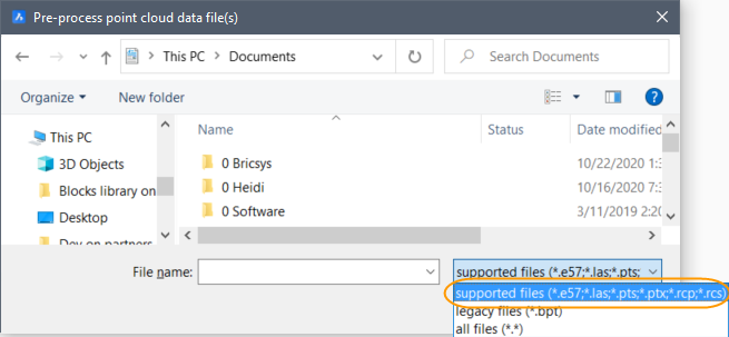
When you attach a point cloud that requires pre-processing, it converts 5 to 8 times faster in BricsCAD v21 than in v20.
The log file can be found in C:\Users\USERNAME\AppData\Roaming\Bricsys\BricsCAD\V21x64\en_US\PointCloudCache\{Folder_for_processed_pointcloud}, only if this path is set in POINTCLOUDCACHEFOLDER system variable. Inside this folder, the current state of processing can be observed.
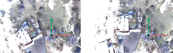
Alignment
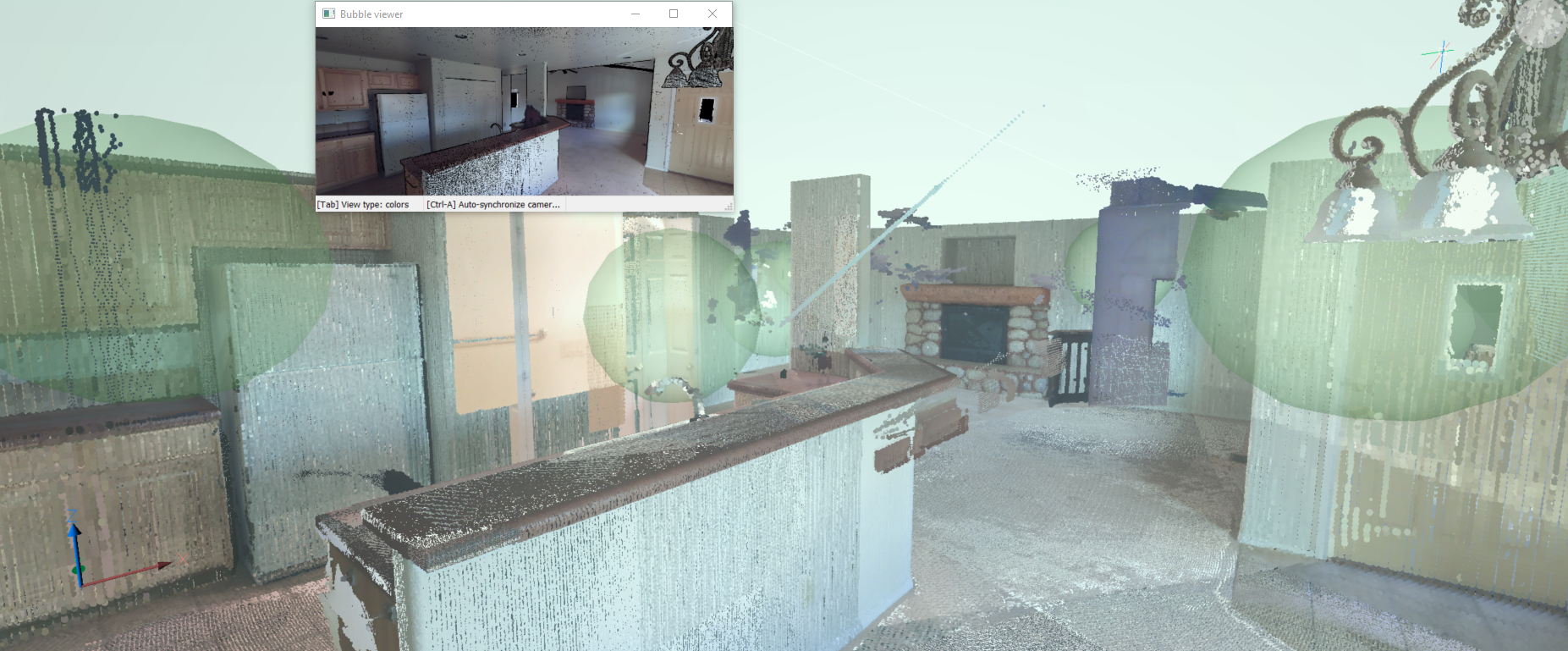
Bubble Viewer
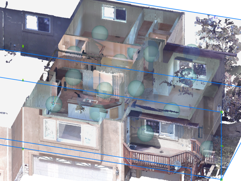
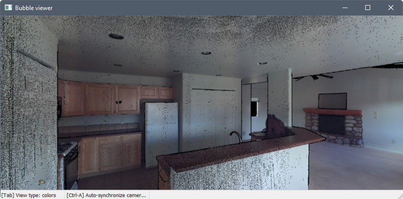
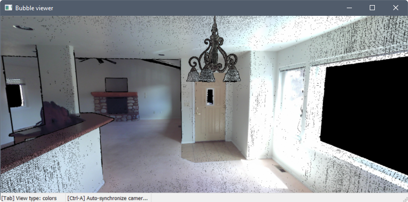
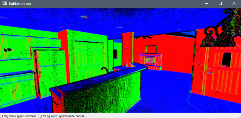
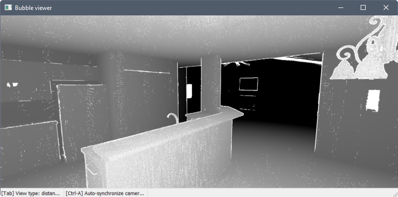
Press the Tab key to cycle between three different visual modes.
The first mode displays the points as their actual colors or in greyscale, depending how the data was scanned.
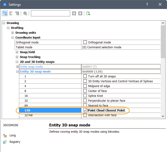
Entity snaps
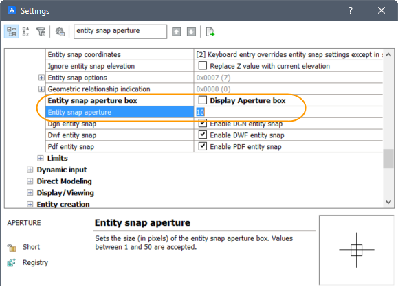
Enable the new Point Cloud Nearest Point entity snap along with other 3D entity snaps in the Entity Snap menus, toolbar, and settings.
Export
The new POINTCLOUDEXPORT command allows you to export a cropped selection of a point cloud to a .pts file.
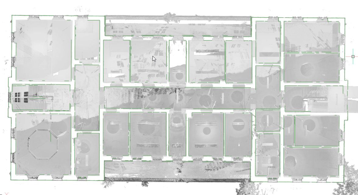
Floor Detection
SectionPlanes work on point clouds as well, they can be used to show parts of point clouds. The difference between point cloud crops and SectionPlanes is that point cloud crop only clips the point cloud while section planes will clip all geometry in your drawing.
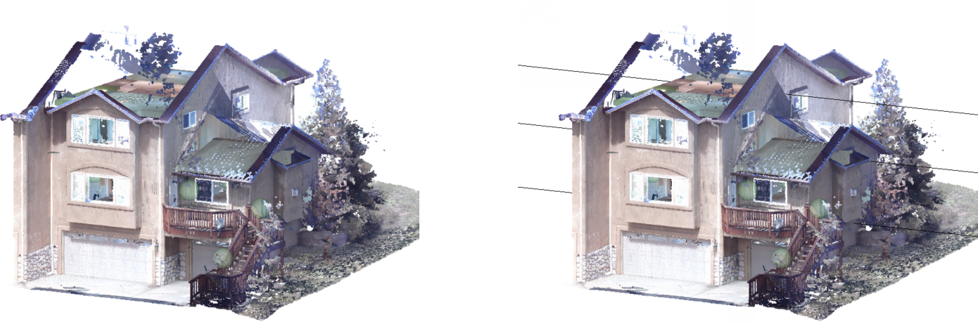
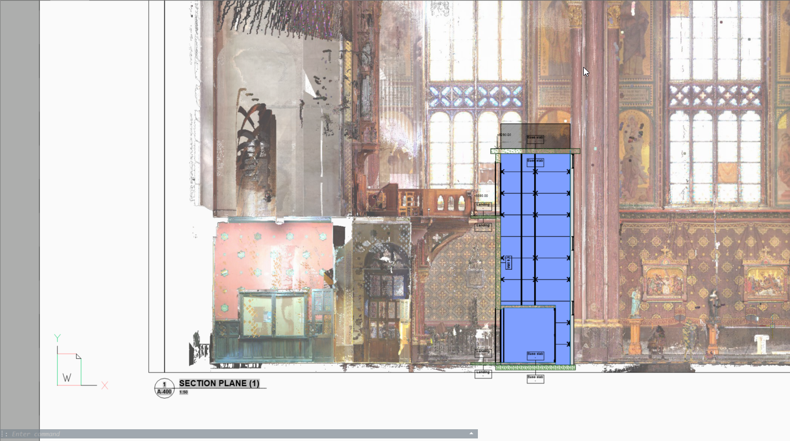
Point cloud projection
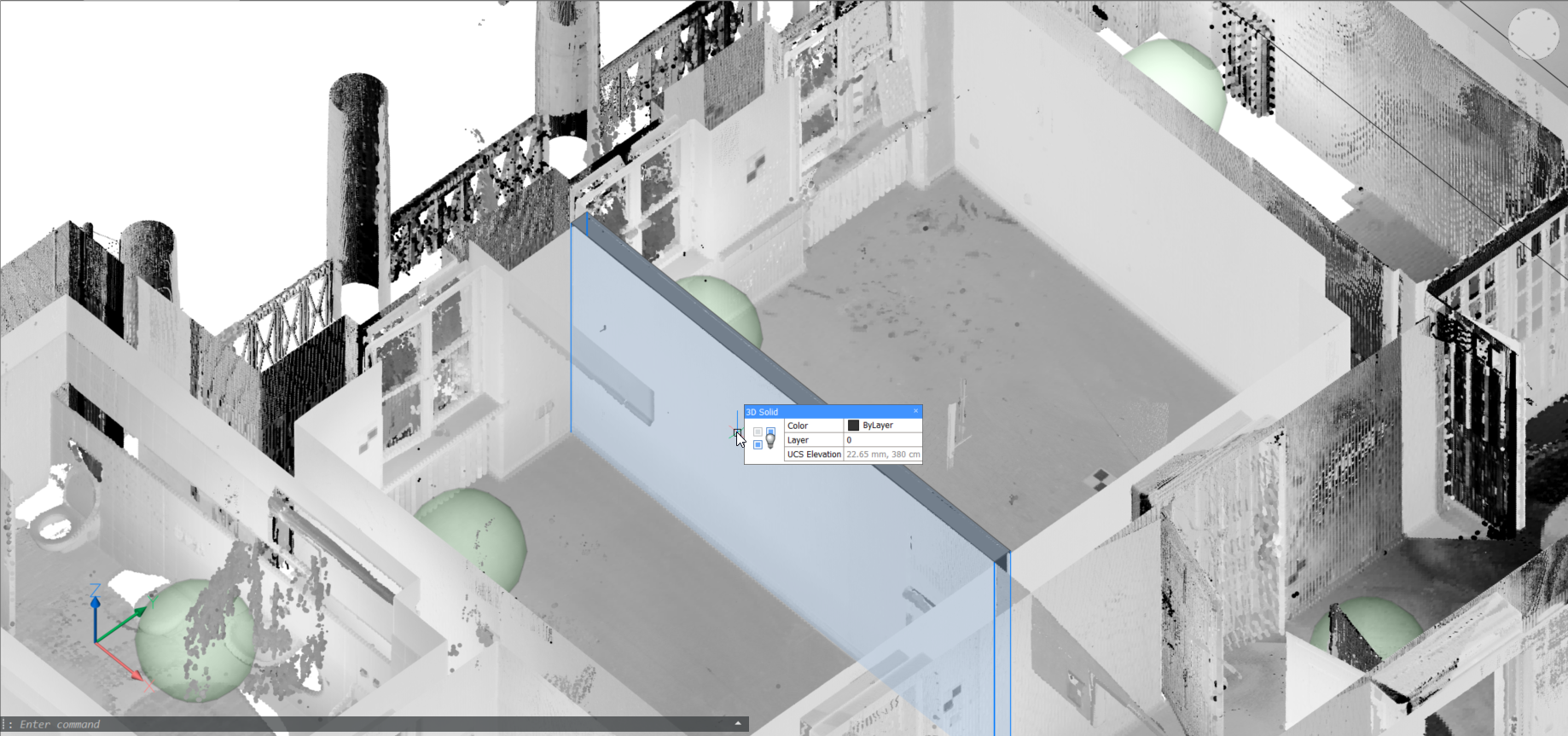
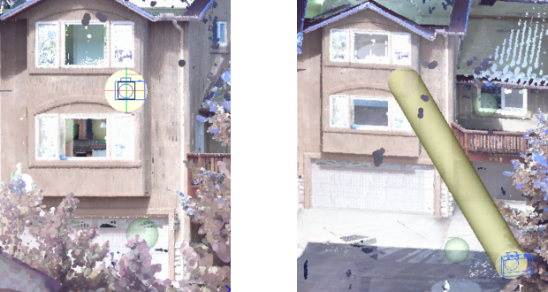
Planar Fit
The new POINTCLOUDFITPLANAR command enables you to create 3d geometry based on the point cloud. It will create a planar surface or solid after a selection of one point in a point cloud. The points that seem to be in a plane are never exactly in one plane, therefore a threshold value is set as a property of the point cloud entity. This also works in bubble view.
In bubble view
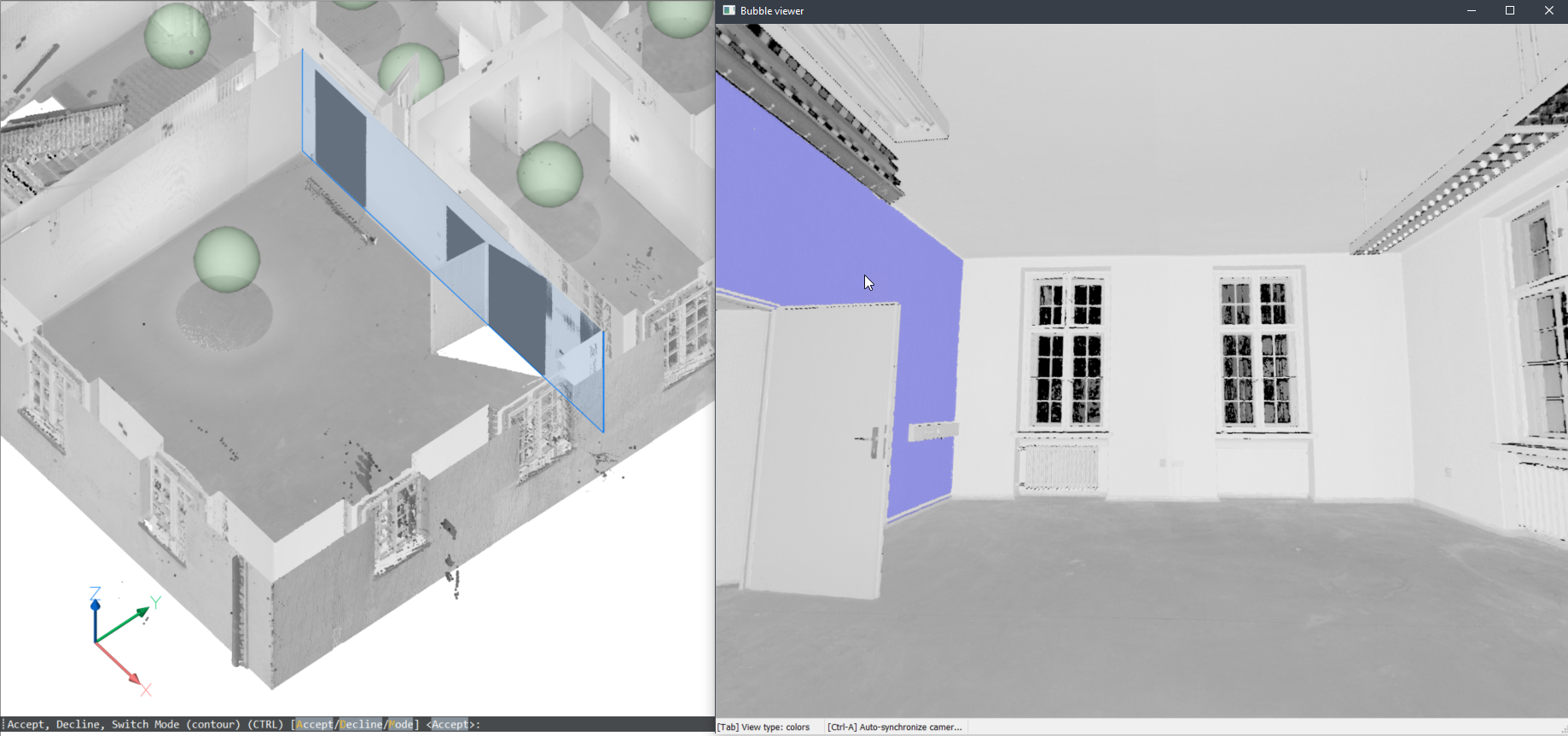
In model space
You can also use this command in the model space when the bubble viewer is not open. BricsCAD will ask you to select a point of the point cloud in model space. Depending on the size of the cropped point cloud, it takes more time, but it has 2 advantages by searching multiple scan positions:
- It can create larger surfaces where only parts are visible in each scan position
- It can detect wall and slab thickness since it can take the opposite surface into account.