AMBOMSETTINGS command
Launches the BOM Settings dialog box.

Icon: 
Method
- There are two use cases to activate the mechanical entities:
-
- When creating a new drawing that contains mechanical entities:
- Set the LOADMECHANICAL2D system variable to ON (1).
- Start a new drawing using a Mechanical2d template.
- When opening a drawing that contains mechanical entities:
- Set the LOADMECHANICAL2D system variable to ON (1).
- Open an existent ACM drawing and start special symbols creation.
- When creating a new drawing that contains mechanical entities:
Opens the BOM Settingsdialog box.
Configures part references (Part References) properties and set up default properties for parts lists, and data capture for the BOM.
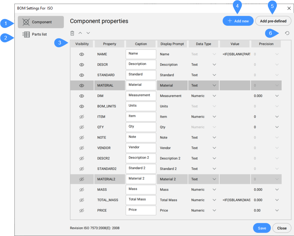
- Component
- Parts List
- List of properties
- Add new
- Add pre-defined
- Restore defaults
Component
Contains a list of component properties that are visible in Part Reference. More properties can be selected by pressing the Ctrl / Shift key.
Above this list there are delete, move up and move down icons, which are available only when a row is selected or the selected row(s) can be moved up or down.
- Visibility
- Toggles the visibility of the property.
- Property
- Displays the name of a component property. This unique name is the one by which a BOM column is referred to in formulas.
- Caption
- Defines the column header to be displayed for this property in a BOM table or parts list.
- Display prompt
- Displays the chosen column header to be displayed for this property in a BOM table or parts list.
- Data type
-
Defines the data type for the property (Numeric or Text)
- Value
-
Defines the default value for the property.
- Precision
- Defines the precision for the property.
Parts List
Contains a list of Parts list properties that are visible in Parts Lists, by default.
In addition to Component properties settings, the following properties are available:
- Caption Align
- Defines the column header position in the cell.
- Value Align
- Defines the value position in the cell.
- Width
- Defines the width of the cell.
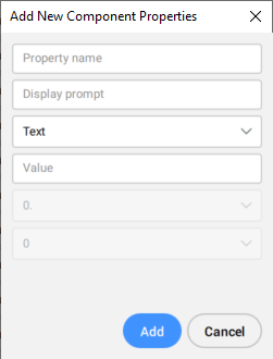
Add new
Adds new component properties as columns to BOM. Opens Add New Component Properties dialog box:
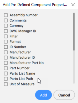
Add pre-defined
Adds new pre-defined component properties columns to BOM. Opens Add Pre-Defined Component Properties dialog box:
Restore defaults
Resets all settings to the default value for the current drafting standard.