BMASSEMBLYINSPECT command
Evaluates the capability of a mechanical assembly to be disassembled or assembled without collisions by respecting a given rule.

Icon: 
Description
Evaluates criteria on a given assembly sequence to assess the ability to assemble your design.
Method
Choose whether to use the panel to specify the sequence or to define it in the Command line.
Assembly Inspect command context panel
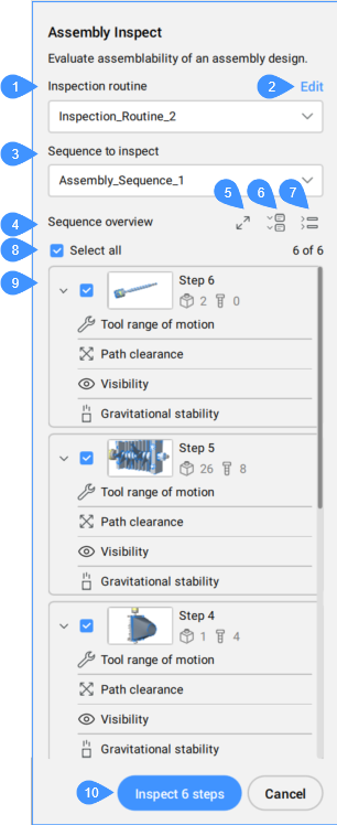
- Inspection routine
- Edit
- Sequence to inspect
- Sequence overview
- Thumbnail toggle button
- Expanded steps display
- Collapsed steps display
- Select all
- List of steps in the selected sequence
- Inspect x steps
- Inspection routine
- Displays the current routine selected from the drop-down list.
If no routine is available, open the Manage routines from the drop-down list to create one.
- Edit
- Opens the Routine editor dialog box to edit the selected routine.
- Sequence to inspect
- Allows you to select a sequence to inspect from the drop-down list.
- Sequence overview
- Displays all steps of the selected sequence.Note: You can select steps one by one or all together (Select all).
- Select all
- Selects or deselects all steps from the sequence at once.
- Thumbnail toggle button
- Switches between small and large thumbnails.
Small thumbnails give you a quick and compact overview of the sequence and assembly results, while large thumbnails allow you to navigate through the sequence and make it easier to find a specific step for activation and inspection.
- Expanded steps display
- Displays all steps in details.
- Collapsed steps display
- Collapses the displaying steps in details.
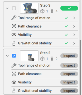
- List of steps in the current sequence
- Displays all steps of the current sequence.
Each step can be selected individually, has a graphic representation (thumbnail), and a list with the criteria for evaluation. Also, the total number of parts and fasteners are shown for each step.
The thumbnails and actual active space during BMASSEMBLYINSPECT respect the orientation of the step in the inspected sequence.
Criteria are applied to the assembly by respecting the step orientation (calculation, model space visualization, and temporary graphics).
By pressing the Inspect button, you can run the evaluation for an entire step or for each criterion from the used routine.
- Inspect x steps
- Runs the criteria included in the routine for evaluating all selected steps.Note: You can Stop the evaluation process any time.
The result of the inspection provides information about how was evaluated each step.
A warning symbol is shown next to a specific criterion in a specific step in case of:
- No fasteners in the Tool range of motion criterion.
- No tool-fastener mappings in the Tool range of motion criterion.
- No parts in the Path clearance criterion.
- No parts in the Visibility criterion.
- No parts in the Gravitational stability criterion when the "ignore fasteners" option is enabled.
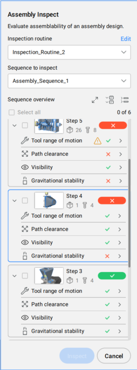
For each criterion from the routine, there is a graphic representation of the result of the evaluation. Depending on the acceptance range set for each criterion, the result of the evaluation is displayed in corresponding colors.
Press the right-side arrow for detailed results. Some evaluations have passed, and others have errors. You can see easily where the error occurs by pressing the Zoom button.
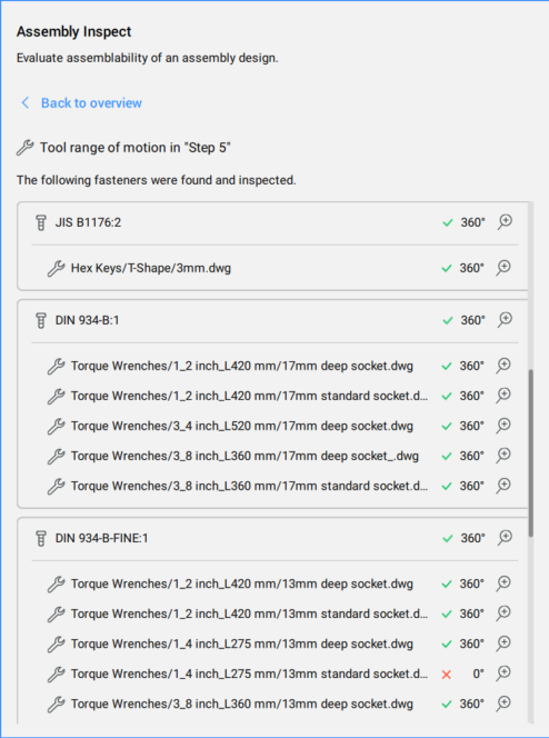
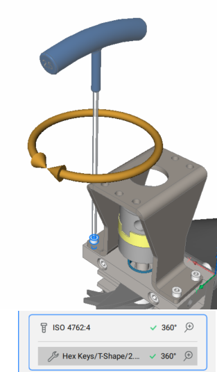
Example of the result of the Tool range of motion evaluation:
In the detailed results panel of the Tool range of motion criterion, each applicable tool is listed with its angular range for each listed fastener. The largest angular range of all tools applicable to this fastener defines the angular area of a fastener.
Example of the result of the Path clearance evaluation:
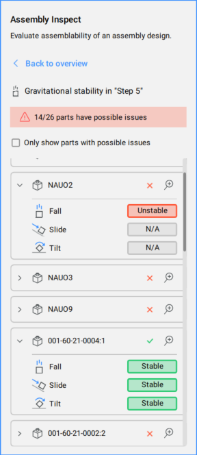
Example of the result of the Gravitational stability evaluation:
Options within the command
You can run the assembly inspect by selecting an option from the Command line.
- Run current routine
- Runs the current routine.
- Cancel
- Cancels the running the routine.
- Exit
- Exits the command.