Routine editor dialog box
Opens via: Manage Routines (BMASSEMBLYINSPECT) dialog box
The Routine editor dialog box allows you to create criteria that will be taken in consideration in Assembly Inspect tool.
All fastener settings and each of the assembly criteria are stored in a routine JSON file that can be imported or exported, allowing routine files to be shared between different users.
- Routine name
- General settings
- Criteria
Routine name
Specifies the profile name under which the rules are grouped.
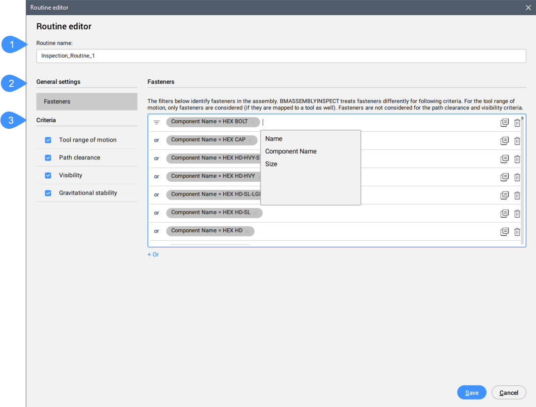
General settings
Allows you to create a Fasteners pre-configuration tools.
- Fasteners
- Defines filters for identifying fasteners in the assembly. The BMASSEMBLYINSPECT command treats fasteners differently for following criteria. For the tool range of motion, only fasteners are considered (if they are mapped to a tool as well). Fasteners are not considered for the path clearance and visibility criteria.
Criteria
There are four category of criteria which will be taken in consideration for inspection of the assembly.
- Tool range of motion
-
- Acceptance range
- Tools
- Tool mappings
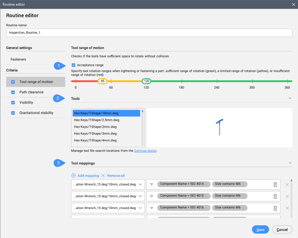
Evaluates whether tools have sufficient maneuverability space. For example, whether each fasteners have enough space to be handled with the specific tool.
- Acceptance range
- Specifies the tool rotation ranges when tightening or fastening a part: sufficient range of rotation (green), a limited range of rotation (yellow), or insufficient range of rotation (red).
- Tools
- Lists the available tools (a range of standard hex keys and one screwdriver) stored in the installation folder C:\Program Files\Bricsys\BricsCAD V25 en_US\UserDataCache\Support\en_US\DesignLibrary\Tools which are loaded automatically as tools.
- Tool mappings
- Allows you to define multiple tool-fastener mappings in order to evaluate multiple tools per fastener.
- Add mappings
- Allows you to add mappings.
- Remove all
- Removes all mappings.
- Path clearance
-

Evaluates whether each part or fastener can be easily added and removed in the current step without collision along the directions of the six local coordinate axes, called the X, Y, and Z "local axes".
- Acceptance range
- Specify the clearance ranges when a part is added or removed: the path is clear of obstacles (green), the path is partially restricted (yellow), or the path is blocked (red).
- Visibility
-
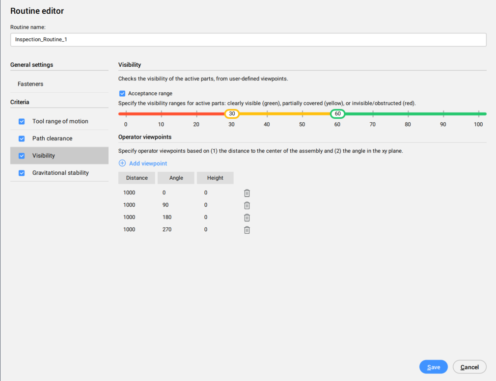
Evaluates the visibility of the active parts from the user-defined viewpoints. The operator viewpoints are defined by the distance to the center of the assembly and the angle in the XY plane.
- Acceptance range
- Allows you to specify the visibility ranges for active parts: clear visible (green), partially covered (yellow), or invisible/obstructed (red).
- Add viewpoint
- Adds viewpoint for visibility check.
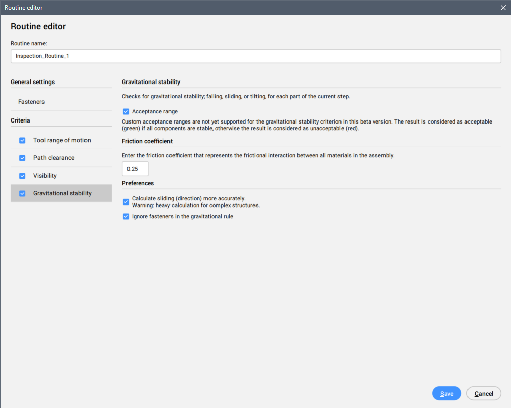
- Gravitational stability
-