


Dynamic blocks
If you come from an AutoCAD® design environment, you may be familiar with dynamic blocks. You may also be familiar with 2D parametric constraints. They are two different functionalities that somewhat overlap.
AutoCAD® dynamic blocks and BricsCAD® parametric blocks are blocks which automate repetitive tasks by allowing users to create one block instead of many similar, separate block definitions. These blocks contain not only pure geometry, but also some metadata, which affect the geometry (e.g., their size, visibility). The metadata controls the way the components of the block behave. Thus, the size and appearance of these blocks can be modified without editing the block definition. Constraints work in the same way for parametric blocks as they do with dynamic blocks.
Dynamic block definitions in Experimental mode
With the Experimental mode activated, you can create and edit dynamic block definitions directly in BricsCAD®.
Disclaimer

Creating and editing dynamic block definitions under BEDIT in Experimental mode is an experimental feature which may not yet be stable, and could be removed in the future.
Use the MANAGEEXPERIMENTALFEATURES command (or the EXPERIMENTALMODE system variable) to turn on or off experimental features, then restart BricsCAD®.
The Experimental mode is turned off by default.
Create dynamic block definitions in Experimental mode
- Turn on the Experimental mode using the MANAGEEXPERIMENTALFEATURES command (or set the EXPERIMENTALMODE system variable's value to 1), then restart BricsCAD®.
- Create the geometry for a new block definition (static) and save it using the BLOCK command.
- Run the BEDIT command to open the Create or Edit Block Definition dialog box.
- Select the Dynamic edit mode and click Ok.
The Block Editor opens.
- While in the Block Editor, add a parameter to the (static) block definition using the BPARAMETER command.
- Associate an action with the parameter using the BACTION or BACTIONTOOL commands.
- Click the Close and Save button to end the bock editing mode and save the changes (the Save option in the BCLOSE command).
The block definition becomes dynamic.
Edit dynamic block definitions in Experimental mode
In Experimental mode, BEDIT supports dynamic block editing mode, in addition to the existing parametric editing mode. Static blocks can be edited in either mode and kept static. Existing dynamic and parametric blocks can only be edited in their respective BEDIT mode. The BEDITMODE system variable (Read Only) specifies the edit mode in which the Block Editor is open. Constraint parameters are visible when present but they are not yet supported.
Use the BESETTINGS command to access the Block Editor settings section of the Settings dialog box.
To edit dynamic block definitions in Experimental mode:
- Turn on the Experimental mode using the MANAGEEXPERIMENTALFEATURES command (or set the EXPERIMENTALMODE system variable's value to 1), then restart BricsCAD®.
- Run the BEDIT command to open the Create or Edit Block Definition dialog box.
- Select the Dynamic edit mode and click Ok.
The Block Editor opens to let you edit the block definition.
- Use the BESETTINGS command to edit the Block Editor settings.
- Use the following commands to edit dynamic block definitions (available only for the Dynamic edit mode):
- BPARAMETER to add a parameter with grips.
- BACTION and BACTIONTOOL to add and associate an action to a parameter and define how the block geometry moves or changes in a dynamic block reference when the action is triggered (the custom properties of a block reference are manipulated).
- BACTIONSET to redefine the selection set of entities for (the geometry to be affected by) an action.
- BGRIPSET to edit or reset the position of grips of a parameter.
- BASSOCIATE to associate an action with a parameter.
- BTABLE to create a dynamic block properties table.
- BCONSTRUCTION to convert entities to construction geometry.
- BVSTATE to manage visibility states.
- BVSHOW and BVHIDE to manage the visibility of entities in visibility states.
- Use the BTESTBLOCK command to temporarily exit the Block Editor and test the dynamic block in the Test Block Window.
- Click the Close and Save button to end the bock editing mode and save the changes (the Save option in the BCLOSE command).
Dynamic blocks vs. parametric blocks
When not in the Experimental mode, if you insert AutoCAD® dynamic blocks into your BricsCAD® drawing, in most cases you can edit those block references. However, you cannot create or edit dynamic block definitions in BricsCAD®. Here, BricsCAD® focuses on parametric blocks to allow you to create both 2D and 3D parametric block definitions using the same set of tools and workflow. It also allows you to convert some dynamic block definitions to parametric block definitions.
When not in the Experimental mode, BricsCAD® partly supports dynamic blocks. You can:
- Insert dynamic blocks from your existing dynamic blocks libraries.
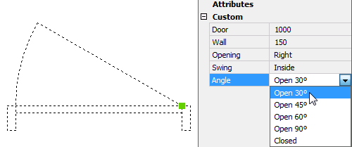
- Edit the custom properties in the Properties panel.
- Use the custom properties of all parameter types and visibility states in fields.
- Grip edit dynamic blocks.
Edit dynamic block references
- Select the dynamic block in the drawing.
The properties of the selected block are displayed in the Properties panel.
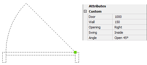
- Under Parameters, edit the properties needed.
The dynamic block is updated automatically.
Grip edit dynamic block references
- Select the dynamic block in the drawing.
The following grip types are displayed:
- Point
- XY
- Linear
- Polar
- Rotation
- Flip
- Visibility
- Alignment
- Drag a grip to edit the block.
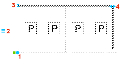
In the example below:
- Rotate the block (1): drag the grip to rotate the block dynamically or type a value in the dynamic entry field.
- Show/hide entities (2): click to select an option.
- Flip (3): click to mirror the block.
- Edit the length (4): select the grip to dynamically edit the length or type a value in the dynamic entry field.
Convert dynamic block definitions to parametric block definitions
Some AutoCAD® dynamic block definitions can be converted to BricsCAD® parametric block definitions by using the BLOCKCONVERT command. For more information, see the article BLOCKCONVERT command.
- Dynamic block features supported for conversion
-
- visibility actions
- one-grip stretch action
- one-grip move action
- chained actions
- rotate action
- flip action
- array action
- alignment action parameter
- scale actions associated with a linear parameter
- scale actions associated with an XY parameter
- lookup action
- history-dependent actions
- block table feature
- linear parameters with two grip points, one of which is not used
- the base point parameter
- move and stretch actions associated with a polar parameter
- polar stretch actions associated with a polar parameter
- interactions between a polar stretch action and a move or a flip action
- actions associated with polar parameters with 2 grip points
- action parameters and dimension constraint parameters of list type
- dimension constraint parameters of increment type
- dynamic blocks with multiple actions associated with a single parameter
- actions with their start point on the X- or Y- axes
- Parametric block features used to reconstruct dynamic block features
-
- visibility states
- parametric move operation
- parametric stretch operation
- parametric rotate operation
- parametric scale operation
- linked behavior of parametric operations
- parametric flip operation
- reference curves
- design tables
- parameter formulas
- associative arrays